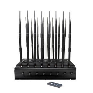
cell phone jammer block diagram
The Cell Phone Jammer Block Diagram is a schematic diagram of the components and structure of a cell phone jammer. These jammer devices are designed to interfere with the signal transmission between a cell phone and its respective base station. By transmitting RF signals at the same frequency as the cell phone, the jammer blocks the communication link, making it impossible for the cell phone to make or receive calls, send text messages, or access the internet.
The basic components of a cell phone jammer block diagram typically include:
- Power supply: The power supply provides the power required to operate the jammer.
- Antenna: The antenna transmits the jamming signal to interfere with the cell phone signal.
- RF amplifier: It amplifies the RF signal to ensure effective jamming.
- Signal generator: The signal generator generates the jamming signal on the desired frequency band.
- Control circuitry: The control circuitry manages the operation of the jammer, including turning it on/off and adjusting the jamming frequency.
- Cooling system: Some jammers employ a cooling system to prevent overheating during prolonged use.
- Benefits of Cell Phone Jammer Block Diagram:
- Enhanced security: Cell phone jammers are often used in sensitive areas such as prisons, institutes, and government facilities to prevent unauthorized communications that could compromise security.
- Privacy protection: In places where privacy is critical, such as corporate board rooms or confidential meetings, jammers ensure that sensitive conversations cannot be intercepted via mobile devices.
- Prevent Interference: In educational institutions, theaters, and libraries, cell phone jammers help maintain an interference-free environment, preventing interference caused by ringing phones or loud conversations.
Other Similar Popular Jammer Tags
| cell jammer circuit diagram | cell jammer schematic | cell phone detector and jammer project | cell phone jammer aliexpress |
-
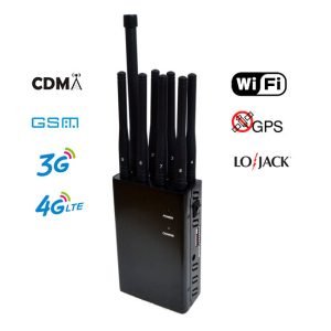
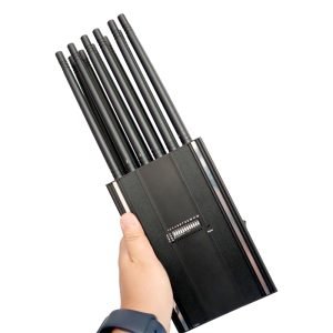
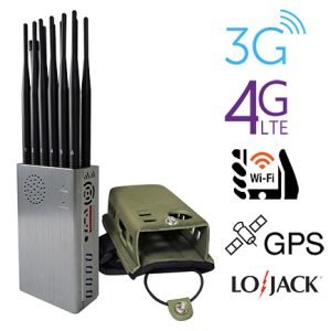
4G Jammer Hot Sale 8 Antenna Portable Handheld Cell Phone Signal Blocker
Original price was: $599.00.$219.99Current price is: $219.99. -
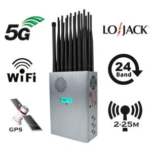
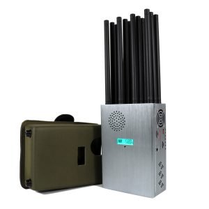
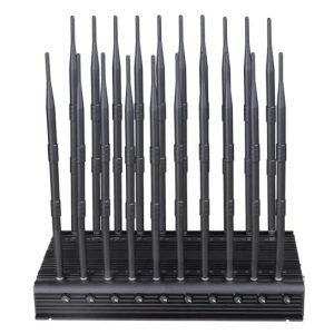
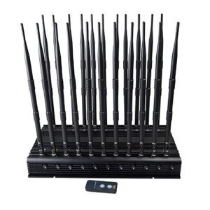
World First Portable 24 Antenna Full Frequency Jammer Blocks All Signals
Original price was: $1,599.00.$829.88Current price is: $829.88. -
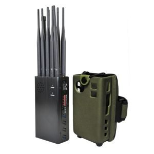
Handheld 4G 5G Jammer VHF LOJACK WiFi GPS 16 Antenna Interceptor High Performance
Original price was: $1,539.00.$839.99Current price is: $839.99. -
Multifunctional WIFI 2G 3G 4G 5G Cell Phone Signal Jammer
Original price was: $599.00.$369.69Current price is: $369.69. -
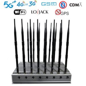
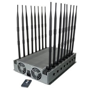
High Power Handheld 12 Antennas 5G Cellphone Signal Jammer 37 Watts
Original price was: $1,299.00.$759.99Current price is: $759.99. -
High Power 12 Antenna 3G 4G 5G Cell Phone Signal Jammer
$729.99 $749.99Price range: $729.99 through $749.99 -
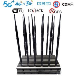
16 Antenna Full Band Signal Jammer WIFI GPS LOJACK UHF VHF Phone Blocker
Original price was: $2,399.00.$1,719.19Current price is: $1,719.19. -
Hidden Antenna 16 Bands 5G Phone Jammer 4G 5G Wi-Fi GPS RF LOJACK Blocker High Power
$759.99 $789.88Price range: $759.99 through $789.88 -
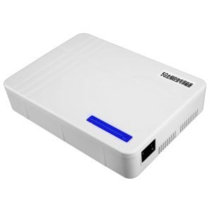
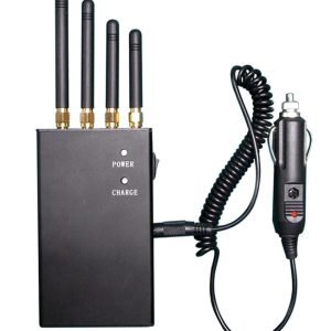
Portable Mobile Power Design Mini Hidden 4 Antennas GSM GPS Jammer
Original price was: $239.00.$139.99Current price is: $139.99. -
GSM 3G (UMTS) WIFI GPS Mini Cell Phone Jammer
Original price was: $169.00.$99.66Current price is: $99.66. -
High Power 16-Band Adjustable Mobile Phone Frequency Signal Jammer
Original price was: $1,899.00.$1,166.99Current price is: $1,166.99. -
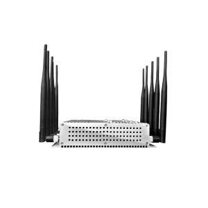
High-Power 10 Antenna Portable GPS Wi-Fi 315 433 868mhz GSM 3G 4G Mobile Phone Signal Jammer
$605.88 $650.99Price range: $605.88 through $650.99 -
18 Channel WiFi VHF UHF Lojack GPS Mobile Cell Phone Signal Jammer
Original price was: $1,399.00.$719.88Current price is: $719.88. -
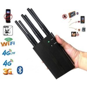
The Latest 8-Antenna Handheld GSM 4G Jammer has the ability to intercept WIFI GPS Signals
Original price was: $499.00.$301.99Current price is: $301.99. -
Portable GPS WIFI Signal Jammer with Shielded Signal GSM
Original price was: $299.00.$168.69Current price is: $168.69. -
New Portable 12 Band WiFi Cell Phone Jammer 315/433MHz
Original price was: $999.00.$649.99Current price is: $649.99. -
World First 20-Antenna All-In-One 5G Mobile Phone Signal Jammer, Shielding 3.5G 3.7G Full Frequency Band
Original price was: $1,399.00.$749.99Current price is: $749.99. -
6 Antennas Cell Phone Signal Jamming Device WIFI GPS GSM 3G CDMA DCS 4G
Original price was: $429.00.$199.99Current price is: $199.99. -
Latest High Power Desktop Signal Jammer VHF UHF WIFI GPS 5G 4G 3G
Original price was: $1,399.00.$719.89Current price is: $719.89. -
Aluminum Alloy Shell 10 Band 5G Mobile Phone WiFi Signal Jammer
Original price was: $699.00.$425.99Current price is: $425.99. -
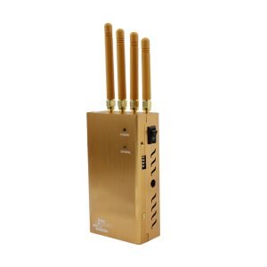
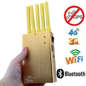
Glod 4 Antenna Jammer Interceptor WIFI GPS GSM UMTS 315 433 868mhz Signal Optional
Original price was: $319.00.$169.66Current price is: $169.66. -
Desktop 16 Adjustable Antennas Jammers LOJACK UHF VHF 2G 4G 3G 5G GPS WIFI Blocker
Original price was: $2,299.00.$1,659.99Current price is: $1,659.99. -
Full Band 22 Antenna Cell Phone Signal Jammer 5G GPS WiFi Blocker
Original price was: $1,519.00.$789.88Current price is: $789.88. -
Desktop 5-Band Adjustable Jammer for 3G 4G GSM WIFI GPS Frequency
$316.89 $385.48Price range: $316.89 through $385.48 -
Plus High Power 12 Antennas Mobile Phone Signal Jammer Portable RF WiFi GPS Signals Blocker
$569.99 $699.88Price range: $569.99 through $699.88 -
The Latest Handheld High Power WIFI GPS 4G Mobile Phone Signal Jammer
Original price was: $769.00.$426.69Current price is: $426.69. -
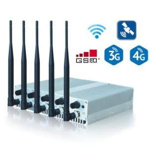
5 Band Jammer GSM 3G GPS WIFI Bluetooth 5 Antenna Video Signal Blocker
Original price was: $399.00.$209.88Current price is: $209.88.