Multi-frequency signal jammer manufacturing and debugging precautions
In the growing field of wireless signal shielding equipment, the core components of multi-frequency signal jammers are the modules responsible for shielding multiple frequency signals. Accurately assembling and fine-tuning these modules are key steps in the production and debugging process. So, what precautions should be taken when manufacturing and debugging multi-frequency signal jammers?
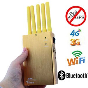
A decade ago, Cell Phone signal jammers were mainly targeted at a limited number of mobile phone standards, such as 2G and 3G, which only required a few frequency bands. At that time, debugging jammers was relatively simple, and technicians only had to adjust four or five shielding modules individually. The process was simple and usually involved using two adjustable potentiometers to fine-tune the frequency offset and bandwidth of each module.
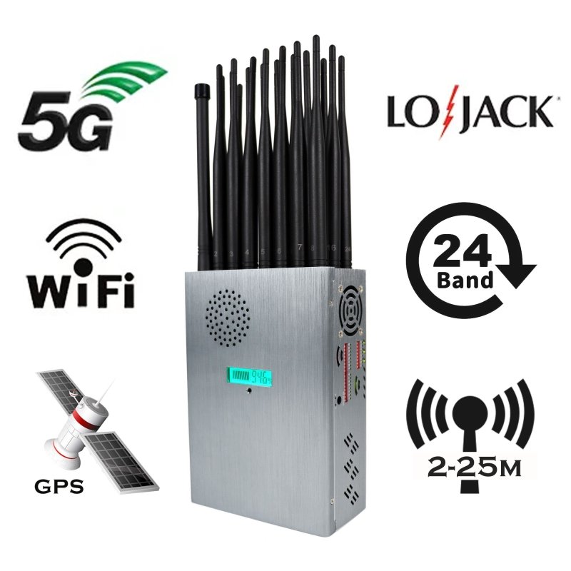
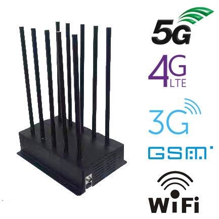
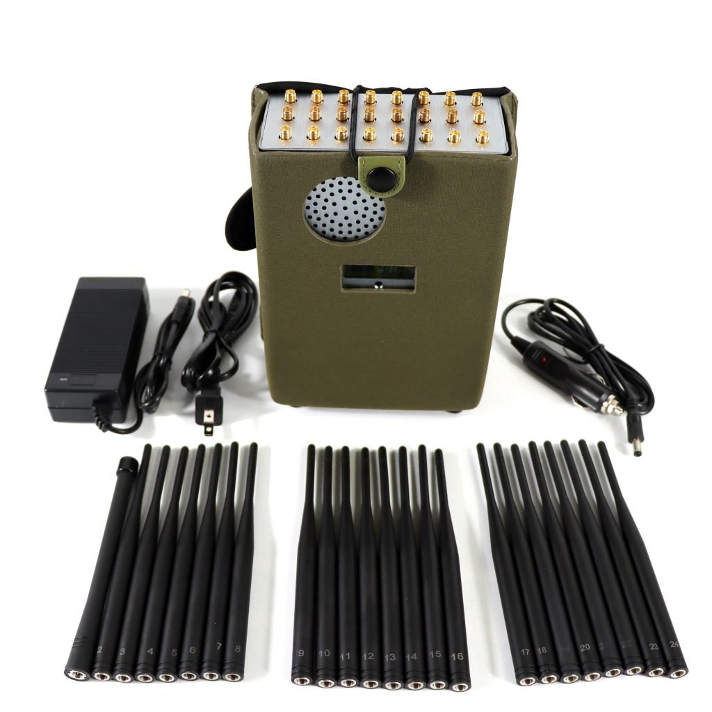
However, modern signal jammers cover a much wider range of frequency bands, often containing 10 or even 20 shielding modules in a single device to effectively block all signals. When dealing with such a large number of modules, the process of debugging and calibrating each module can become time-consuming and laborious, bringing unexpected challenges.
Technicians must adjust the frequency of each shielding module one by one and reset the parameters on the debugging instrument for each subsequent frequency band. This extended debugging time greatly prolongs the entire process. In addition, technicians may encounter frustrating situations where, upon revisiting a previously debugged module, it deviates from the desired output frequency. This requires further calibration and adjustment. These deviations occur due to signal interference between multiple frequency bands and variations in the voltage output of the power board.
To address these challenges, the most effective solution is to use an equivalent number of spectrum analyzers according to the frequency bands present in the multi-band signal jammer. A dedicated equipment debugging test bench should be customized to allow signal debugging of multiple frequency bands at the same time. While adjusting the frequency, technicians can visually observe the waveform display on multiple spectrum analyzers to ensure that each shielding module meets the correct debugging parameters.
By adopting this approach, manufacturers can simplify the production and debugging process of multi-band signal jammers and improve the efficiency and accuracy of achieving the desired signal shielding capabilities.